Startseite » Expertise » Design recommendations » Specifications
We want to use the powder bed fusion (PBF) process to provide you with custom-fit 3D-printed parts of the highest quality. For us to achieve this, it is important that you also understand the process. We would therefore be grateful if you would carefully read the following specifications and design recommendations for 3D metal printing, 3D plastic printing and finishing, as well as our information on quotations and equipment. This information represents the framework for our 3D printing services.
Our 3D-printed metal products are created using the selective laser melting (SLM) process, which involves layer-by-layer local fusion with selective laser radiation of layers of weldable metals in powder form from almost all areas of application.
Due to the high density of the components, mechanical post-processing or even polishing right up to a high-gloss finish are possible.
Dimensions for metal components
Metal components measuring up to 400 x 400 x 360 mm or 400 x 800 x 500 mm (aluminium) can be manufactured in a single operation.
To optimise costs, laser melting can build solid components with different wall thicknesses (hollowed out) depending on their geometry:
Depending on the complexity of the components, the minimum wall thickness may also be increased. Dimensional and shape tolerances depend on the geometry of the components. In most cases, a deviation of +/- 1 % can be assumed. As a rule, production is carried out in accordance with the general tolerance standard DIN ISO 2768-m.
Fittings and threads should always be produced by means of a machining finish. The allowance for a machining finish must be at least 0.5 mm (or even higher, depending on the geometry of the component).
“Feel free to discuss these application examples with us. We will be happy to provide you with our advice and assistance.”
Design recommendations:
Support-free setup
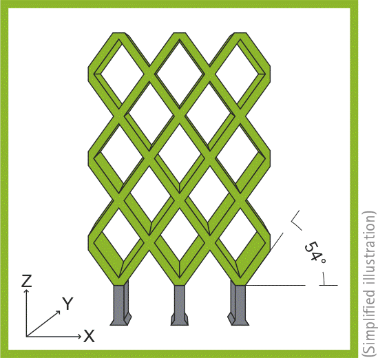
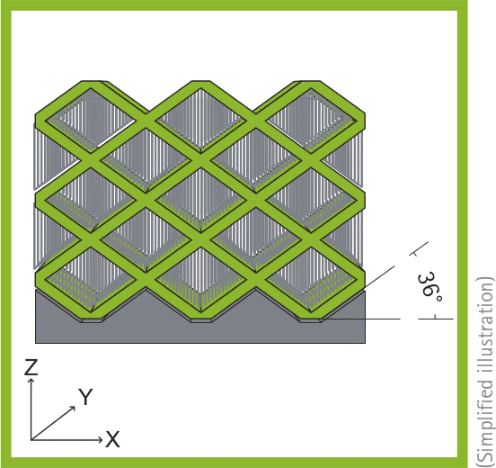
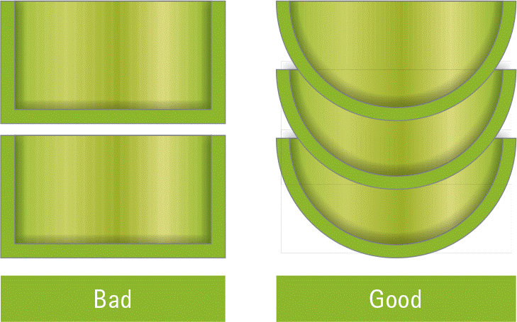
When working with metal, each component must be fixed to the base plate. This fixation is also known as support and is used for both heat dissipation and mechanical stabilisation. Furthermore, support geometry is required at points at which a contour is not melted on a previous contour (but instead into a loose powder bed) or where the area to be exposed deviates very strongly (>45° or a radius of >3 mm) from the previous layer. In most cases, the support structure is a honeycomb structure with the smallest possible wall thickness, which can be easily removed by hand in the outer area of the component. The illustrative images below show how differently a component can be built up in this process and what effects the direction of assembly can have.
On the left, the component (marked in green) is optimally aligned for the process, while the alignment on the right (rotated by 90°) is unfavourable to the process. The grey areas indicate the support structures required.
Hybrid design
When using the hybrid construction method, the component to be manufactured is disassembled into a substructure (hybrid part) and the actual SLM part.
For tool steel 1.2709, the following materials are suitable as base materials for the substructure:
If other materials are to be used as a substructure, stress cracks or detachment of the SLM part from the hybrid part may occur. The use of such materials therefore requires prior technical clarification by FKM.
“FKM recommends using the material 1.2709.”
Our 3D-printed plastic products are created using layer-by-layer local fusion with selective laser radiation of powder layers of materials with an extensive range of properties specially developed for this selective laser sintering (SLS) process.
We also offer the enhancement of surfaces by means of smoothing, colour infiltration or coating.
Dimensions for plastic components
Depending on the material, plastic components measuring up to 910 x 430 x 405 mm in size can be manufactured in one piece in a single operation. By adding individual elements, assemblies of any size can be produced.
If components are too large for our installation space, we cut the CAD data and glue the components together after the construction process. The glued seam can be reinforced with fibreglass mats.
In general, any contour can be produced with plastic laser sintering
With this process, undercuts or film hinges are not a problem – as is perfectly proven by the production of a one-piece laser-sintered whistle with the ball already inside. Internal and external threads from a size of M10 can also be produced, provided that they are built in the Z direction, provided that they are built in the Z direction.
Our SLS process masters the production of film hinges, interlocking parts and more. Contact us to discuss these and other application examples – we will be happy to provide you with further advice.
We generally manufacture with a layer thickness of 0.1 or 0.15 mm. The minimum wall thickness is approx. 0.5 mm in Z and approx. 0.7–0.8 mm for vertical surfaces. Both minimum wall thicknesses depend on the geometry of the component in question. Feel free to contact us to find out more!
Design recommendations:
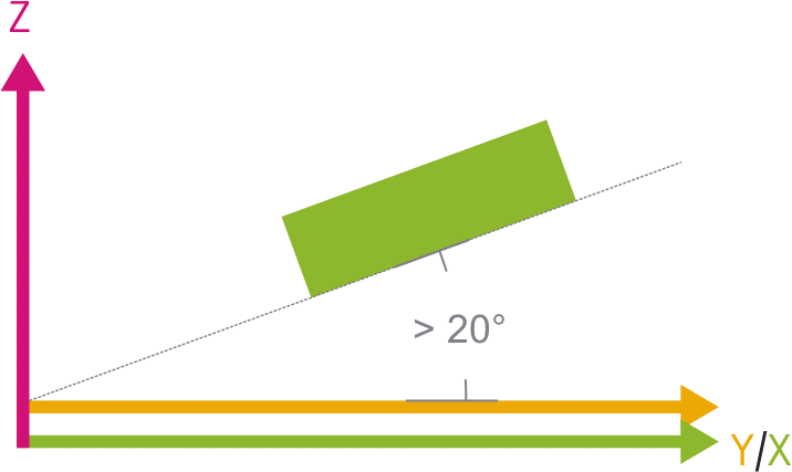
Steps in the component
If a construction plane is aligned with an angle of less than 20° to the X/Y plane, clear layers can be seen on the surface. The steeper the angle, the finer the steps.
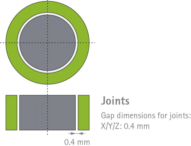
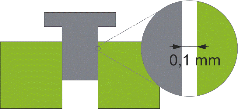
Loose connections
0.1 mm spacing is required for loose connections. Without a gap between a male and female component, a press fit is created.
Powder removal
Residual powder should be removable. but is difficult to remove in the case of long and thin pipes and parts with complex internal structures. The easier the powder can be removed, the shorter the post-processing time.
Tolerances
The tolerances depend on the material used and the component geometry.
In most cases, the following values can be assumed:
Smaller tolerances may be possible depending on the component geometry. In such cases, further consultation with FKM is required. Geometry-dependent distortion is possible because laser sintering is a thermal manufacturing process.
The tolerances specified above do not apply to holes. Bore dimensions are generally slightly smaller than required.
Costs
The costs depend on the overall height (Z direction), which in turn determines machine hours and powder consumption.
Reducing the construction volume
Reducing the overall height:
The price of the components depends on various factors such as size and quantity. The higher the number of units ordered, the lower the price of each individual component. Our quoted prices include a visual and dimensional inspection of the parts.
We ideally need the CAD data from you in order to prepare an offer. In exceptional cases, reference prices can also be quoted based on drawings. We also need to know your required quantity and chosen material. Information regarding your desired delivery date is also helpful.
You can send us your data via the following channels:
Your confidential data will be checked for quality and feasibility after receipt. We are happy to sign a non-disclosure agreement confirming that your data will be handled confidentially.
We work with the STL data format but can also process all common data formats, for example:
We will manufacture the components for you in the best possible building setup and, if necessary, discuss this with you in advance. Your component requirements are the decisive factor behind our manufacturing approach, although the tolerances in laser sintering must also be taken into account. If there are component areas that require special consideration, please inform us beforehand.
Shipping
Shipping within Germany takes place overnight, meaning that you will receive your parts by noon the following day!
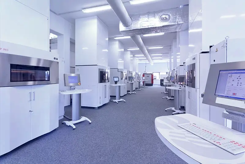
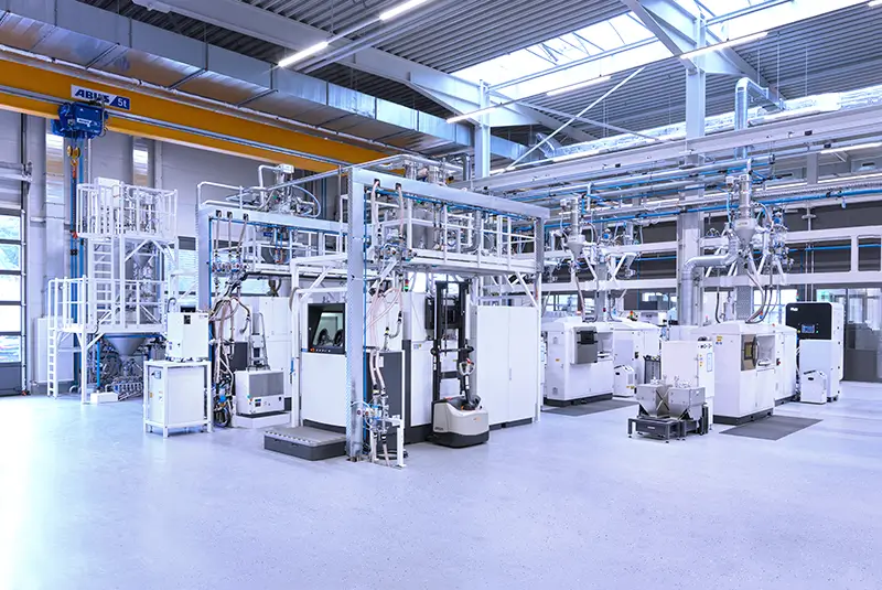
A wide range of equipment is available for our in-house production of your components, namely:
SLS – plastics
|
Type
|
Construction volume
|
|---|---|
|
Small (1 machine)
|
200 x 200 x 300 mm
|
|
Medium (7 machines)
|
375 x 375 x 539 mm
300 x 300 x 550 mm |
|
Large (20 maschines)
|
910 x 430 x 405 mm
660 x 365 x 550 mm 600 x 300 x 500 mm |
SLM – metals
|
Type
|
Construction volume
|
|---|---|
|
Small (2 machines)
|
90 x 90 x 80 mm
|
|
Medium (10 machines)
|
250 x 250 x 310 mm
250 x 250 x 280 mm 250 x 250 x 210 mm |
|
Large (4 machines)
|
800 x 400 x 500 mm
400 x 400 x 400 mm |
Sie haben Fragen?
Nehmen Sie zu uns Kontakt auf.
Do you have any questions?
Please get in touch with us.